Connectors
Preface
Connectors serve as links between two objects (beams) and to freely place a single cnc processing object like a milling or mortise/tenon.
Despite that it is possible to place the connector freely rotated in 3d by using a (temporary) working plane.
Beam provides several methods (buttons) to place a connector on its sides and ends.
Parameters
Rotation
Rotation around the z-axis
Type
There are currently four types of processing objects implemented.
Width
The width of the beam (y-coordinate in beam dimensions)
Height
The height of the beam (z-coordinate in beam dimensions)
Connector type Contour
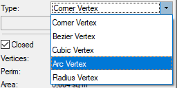
Contour type takes the path geometry of the connector path object to define the milling. Please note, that beside the normal corner vertex
only arc vertex are supported for an export to Elements CAM. Unlike with the other connector types, there's no limit on the number of contour points.

Parameters
Contour Depth
The depth of the contours milling (y-coordinate in beam dimensions)
Connector type Mortise or Tenon
Mortise / Tenon are used widely to connect two beams. In general, a tenon's length is a bit shorter than the depth of the mortise.
Also, a radius may be specified for a mortise with rounded corners.
The tenon is placed around a virtual middle line of the connectors' path contour, and it's dimensions are set through parameters.
Please note, that it has to be defined by a contour with four cornerpoints.
Parameters
Tenon Width
The width of the mortise or tenon parallel to the virtual middle line of the connector
Tenon Length
The length of the tenone or depth of the mortise
Tenon Setback
This is used to equally leave a space to the outer contour on both sides of the mortise / tenon.
In construction, this is used to hide the mortise from viewing.
Tenon Radius
The corner radius for the mortises' milling.
Connector type Drilling or Circular Pocket
This processing object is machined by drilling or milling the workpiece. It has a diameter, depth and also a direction is possible.
Please note, that a drillings' middle point has to be defined by a line with two or a contour with four cornerpoints.
Parameters
Drilling Depth
The width of the mortise or tenon parallel to the virtual middle line of the connector
Drilling Diameter Length
The length of the tenone or depth of the mortise
Drilling Rotation
The rotation at which the angle is applied.
Drilling Angle
The angle of the drillings' direction (other than perpendicular to the surface)
Connector type Arc
An arc is defined by a three points contour, where all points lie on the arc. The first and last point define the outer points of the arc segment,
and the second (middle) point defines the radius of the arc.
Parameters
Circular Arc Depth
The depth of the circular arcs' milling

